I’ve accomplished this little project back in 2016 when I had two Xbox 360 wireless controllers and a huge desire to use them with a PC. To do so, you have to have a wireless receiver, and there were 2 mainstream options on the market:
- a genuine one - the best option, but costs around $60;
- an unofficial replica - can be found for $10-15, but reliability and driver support were quite questionable.
At that moment, I was short of money to get the first one and didn’t want to try luck with the second. Fortunately, if you dive a bit deeper into the topic and doesn’t afraid to do some soldering, there’s a third option - using an RF module from a broken Xbox 360 (later in the text I’ll refer to it just as “RF module”).
If you just want to build your own device, jump straight to the Building the device.
Connecting the RF module
At the moment of working on the project thorough reverse engineering has already been done and documented. The authors figured out that the RF module communicates with Xbox 360 itself via 2 interfaces:
- A proprietary I2C-like protocol, for controlling LEDs and syncing with controllers;
- USB, for communicating with controllers.
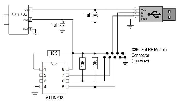
The USB connection is quite straightforward - you need to connect the ground and data lines and supply 3.3 volts for the power. Being connected to the PC, the RF module works exactly like the official wireless receiver, the only difference is the PID of the device, but after manually installing the official driver everything works as it should.
Connecting a control bus is more complicated, but there are a bunch of different options:
- Leave it unconnected. I haven’t tried that, but I’ve read that the RF module will work fine this way with the controllers that have been previously synced with it. I also read that it’s possible to sync a controller by connecting it via Play and Charge Kit to the same computer, but I haven’t verified that too.
- Using a Raspberry Pi. It can be quite handy if you plan to permanently use the RF receiver with Raspberry. It’s even possible to display things using the module’s LED ring, which can be a nice feature.
- Using an FT232RL and a program for Windows. I’ve checked this one, but it didn’t work for me. I tried to attach Saleae logic analyzer to data pins and it seems that my FT232RL’s IO wasn’t fast enough, seems like I’ve got a counterfeit chip. Also, that’s way too cumbersome for everyday use.
- Using an Arduino or a bare microcontroller (also called as MCU) (for example, ATTiny45). As for me, this is the best option since you’re getting a self-sufficient device.
Bringing AVR to the table
I decided to use a microcontroller, and I wanted something that wouldn’t be overkill for this task. Fortunately, I had a few ATTiny13 laying around, which is more than enough for the given task. Also, I had a DIY development board based on ATMega16A, which was quite handy for working on the project.
To be sure that I implemented the communication protocol correctly and that my module wasn’t dead, I wrote the code that received a command via UART and sent it to the RF module. And it worked! Here’s a quick demo:
While testing different commands, I decided that the final implementation should allow to sync a new controller and to disable all the connected controllers. For doing so, I connected the power button from the RF module to the microcontroller too and implemented the following logic:
- After powering up, the MCU waits for 3.5s to allow the module to boot up properly and sends the “LED_INIT” command to initialize the LED ring and turn on the green LED in the center;
- After that, the MCU waits for the button press. On short press, it sends the “SYNC” command to sync with controllers, on the long press - sends the “CTRLR_OFF” command to power off all connected controllers and right after that send a bunch of commands to shortly turn on the led ring for the clarity.
Initially, I implemented the new logic for ATMega16, and when everything was working as intended, I ported it to ATTiny13, which was a matter of just changing a header file and GPIO ports mapping. When the firmware was ready, it was time to build the final device.
Building the device
Here’s the list of what you’ll need to build the standalone receiver:
- An RF module itself. You need the one from the first generation of Xbox 360 (so-called Fat model). Also, pay attention to the revision of the module - people discovered that Rev. A modules from Xenon consoles have problems with Windows 8 and have worse connectivity range, while Rev. B and the rest don’t have those issues. I’ve got a Rev. F module and had zero problems using it with Windows 7 and a wide range of macOS versions. RF modules from Slim and E models aren’t suitable - although people figured out how to connect the USB, the control bus seems to be different;
- AVR microcontroller. The firmware is simple and can be compiled with GCC AVR for any AVR chip with some minor changes. Both source code and the compiled binary for the ATTiny13 are stored in the project repo;
- A way to provide 3.3v power to the module - I used an 1117-33 LDO voltage regulator with filtering capacitors, but any voltage converter can be applied here;
- 3 pullup resistors, their optimal value is 10k ohm, but it will work with slightly different values too;
- A programmer for AVR, a USB connector to your taste, some hooking wire, soldering supplies - the standard stuff.
If you haven’t worked with AVR or with microcontrollers in general, don’t forget that you have to flash the firmware to the MCU. There are plenty of ways to do so, I used FT232RL from the hardware and avrdude from the software side.
Here’s the connection diagram. The RF module’s connector is depicted as if you were looking on the front side of it:
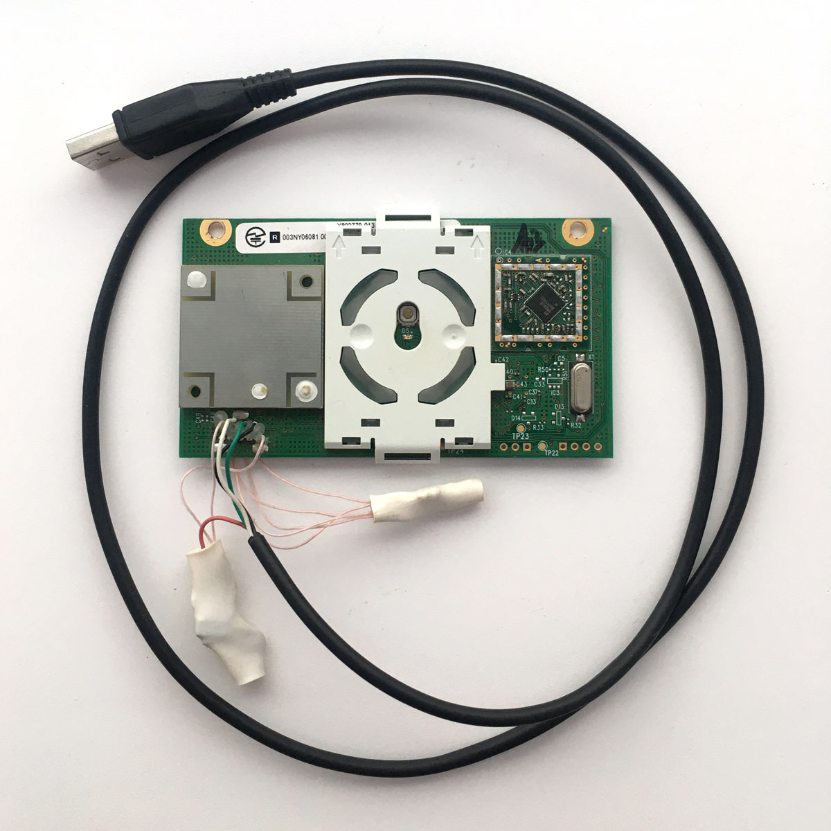
I decided not to bother with making the PCB and connected everything with hooking wires, covering all the dangling components with a heat-shrinking tube. After checking that everything works, I’ve zip-tied the receiver to the bunch of cables on the back of my PC and used it this way until moving to another city. I still have the device, and this is how it looks nowadays:
That’s how my desire to play some games motivated me to build something new!